
Product overview
Front
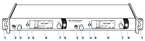
- 1 Rack mount „ear“
- see Mounting the transmitter into a rack
- 2 Headphone socket
- see Using the headphone output
- 3 Volume control for the headphone socket
- see Using the headphone output
- 4 SYNC button
- see Synchronizing devices
- 5 Infrared interface with a blue LED
- see Synchronizing devices
- 6 Display panel
- see Displays on the transmitter display panel
- 7 Jog dial for navigating through the menu
- see Buttons for navigating the transmitter menu
- 8 STANDBY button
- see Switching the transmitter on and off
Back
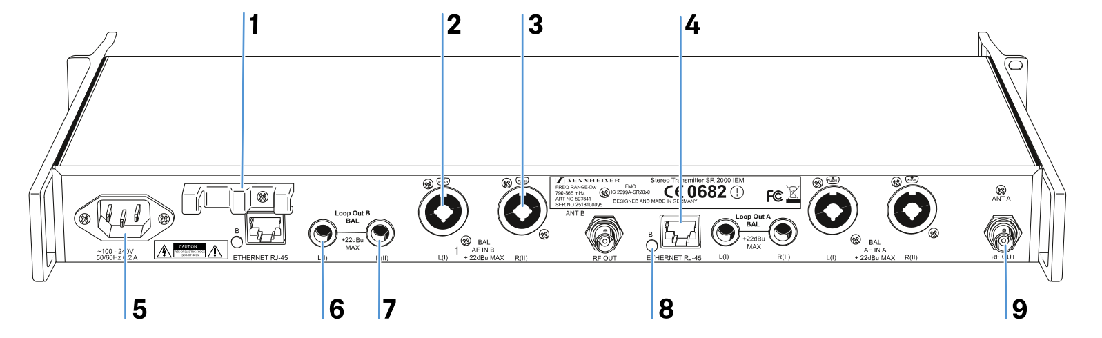
- 1 Cable grip for power supply DC cable
- see Connecting/disconnecting the transmitter with/from the power supply
- 2 ¼" (6.3 mm) jack/XLR-3 combo socket BAL AF IN L(I)
- Audio input, left
- 3 ¼" (6.3 mm) jack/XLR-3 combo socket BAL AF IN R(II)
- Audio input, right
- 4 LAN socket (ETHERNET RJ 45)
- see Creating a data network
- 5 3-pin mains socket
- see Connecting/disconnecting the transmitter with/from the power supply
- 6 ¼" (6.3 mm) jack socket LOOP OUT BAL L(I)
- Audio output, left
- 7 ¼" (6.3 mm) jack socket LOOP OUT BAL R(II)
- Audio output, right
- 8 LED (yellow) for network activity indication*
- 9 BNC socket RF OUT
- ntenna output
* These operating elements are available twice on the SR 2050 IEM twin transmitter and are labeled A and B respectively. A designates the left-hand transmitter, B the right-hand one (seen from the front).